Online Presence Now Moved

25 03 2021

It has been a long while since I have posted here. Life moves on and so has this blog. You can now find all of my new content at AzureFrost.

I will leave everything else here for posterity. But, any future comments will need to be directed to my blog there.

Thank you all and see you on the new platform.


Minor Progress with HAB

8 04 2014

I have started to test this glue for the envelope on my high altitude balloon today. I haven’t found anything else that can glue Polyethylene locally. So, I have decided to see how this stuff goes. The only problem I can foresee is that the joints are too rigid and start cracking. Time will tell though.

I’ve also started to think about launch platform recovery and am going to use an idea one of my friends came up with. That is, make the payload a UAV that can fly itself back after reaching max altitude. To achieve this, I’m first going to make a standard park flyer that I can learn to fly with and, eventually, make it automated. From there, I’ll make a glider that will float up with the balloon, be used to launch the rocket, record and transmit flight data and then glide back to home base. The only issue then would be recovering the rocket. I don’t want to make the rocket and recovery/launch platforms one device, because this will eventually be the format used for launching larger rockets that, hopefully, won’t come back. So, reduction in the weight of the rocket will be crucial to obtain maximum altitude and payload weight.


Production Grinds to a Stop During Holiday Period

23 12 2012

Christmas has meant I haven’t been able to spend any time on my projects. Progress will resume in the new year.


Motor Controller Progress Update

12 11 2012

Don’t worry everyone, I haven’t disappeared off the face of the Earth. Just have been taking my time with my projects and also ran into a lot of snags on the way.

First up is the printed circuit board for the motor control schematic I posted earlier. The design is finished but I have had some troubles getting in made so I can test it. I also have had trouble uploading the KiCAD files for the board onto github in a way that is then downloadable. So, as a result, I am currently moving all of the modules that I used on the board into a single library that can then be downloaded with the board. Hopefully this will fix the problem.

Now, back to the problems I’ve been having getting the board made. Since I am a low income earner, I can’t easily afford to get my designs made by professional board manufacturers and have to rely on my home made boards. I usually use the photo-lithography (also known as photo transfer) method but ran out of the positive resist boards that I have for this purpose. The people who I use to buy these boards from no longer sell them, which means that only the negative resist boards are available locally and they are quite expensive. This led me to find a seller on the opposite side of the country that does sell the positive resist boards I am use to, but they charge $15 for freight up to 3kg, which was almost the same cost of the board itself.

I shelved that idea at that point, mainly due to me being lent a Roland MDX-20 CNC router. This then opened up a bigger kettle of fish. I have had a bit of experience with this machine in the past and gave up on it. This was a result of the bad quality software that comes packaged with it that will only run on windows. This time around, however, I was determined to get something printing from it in an open source environment. I jumped the gun and downloaded the LinuxCNC ISO then installed it on an unwanted old computer I was given by a friend. This didn’t work for me because the Roland router uses a specific language that was derived from HPGL called RML and LinuxCNC does not have the capability to send these commands to it.

After this, I tracked down two pieces of software. The first is a piece of software developed a MIT (link to come) and another called Tux Plot. The MIT software worked but it was very time inefficient and took over two hours before it was even half done on my test piece. I didn’t spend heaps of time on this and it may have just been a configuration issue, but it put me off anyway. Tux Plot didn’t work very well at all. It is meant to convert HPGL to RML then send it to the router. But, it was hard to calibrate and also did some weird conversions, like trying to drill through the entire board at the corners of my design. It also does not convert some of the commands. The HPGL format supports circles and arcs directly but RML does not and you must manually tell it to draw circles and arcs point by point. Tux Plot doesn’t take this into account and just leaves the circle commands in the code without doing anything at all. This results in the router going to the location of the centre of the circle then going down then straight back up without making the circle. The final blow for Tux Plot came when I found out that KiCAD outputs HPGL in a configuration meant for plotters (as it is originally intended) and not for routers. So, where the HPGL file tells the router to go is where a plotter would normally draw with its pen. Instead I have a milling bit that wants to cut stuff away. This results in the tracks being cut away instead of the gaps between them.

It was with this realisation that I knew getting this router to work with KiCAD in a reasonable manner was a project in itself. So, I have given up on it for the current time and will revisit it when I am finished the bicycle. In the mean time, I wrote a post on the hackaday forums trying to organise a group buy for the positive resist boards I found, but have not had anyone reply as of yet. I bit the bullet and spent the money on the negative resist board, just so I can get the project moving again. I think I will have to save up a bit and do a bulk buy myself and sell the excess on ebay, or sell kits of the finished design to use them up.

That’s pretty well where I’m at currently. My next step is to sort out my github issues and manufacture the first prototype of the alpha design for the power section of the motor controller.


BLDC Motor Controller Schematic

11 10 2012

Hi all,

Power section of BLDC motor controller for recumbent electric bicycle.

This is the schematic for the alpha version of the power section within the motor controller I am designing for my electric recumbent. It is fully untested so use at your own risk. It will be run by an Arduino on my project but I have designed it so that nearly any micro-controller with TTL logic levels can be used. I am in the middle of designing the PCB and will upload all of the files to github once I’m finished. Also, an explanation of the circuit will be put up soon too and yes I am aware that the hall effect sensors are missing. I am not sure if I will be adding them to this board or making a separate one for them. If I do add them then I will post an update.

Hope you all enjoy and let me know if I’ve made any silly mistakes or if you think I should add something.

Cheers,

Aaron.


Bare Probe Temperature Test

3 10 2012

I’ve completed a preliminary temperature test with the probe I made on the solar cooker today. All went fairly well, up until the point that I got bitten by a green ant in between my toes during one of the measurements. This resulted in me accidentally pulling the probe off of the cooking rack and, hence, ending the experiment prematurely. I did get good results none the less.

Bare probe on the cooking rack

One thing that I did note is that the wind had a big effect on my temperature readings. As can be seen in the data plot below, whenever a small breeze came up, the temperature would drop dramatically.

Graph of temperature readings during the test.

This makes me want to redo the experiment with the probe inside a glass jar, with possibly a slight vacuum applied. This way I can get some more accurate results and some more extreme temperatures if I apply a vacuum.

Bare Probe Test Data

As mentioned during the post on building the probe, I think that the temperature readings I am getting are lower then the actual temperature because of the exposed bit of the probe. Before the experiment was brought to a premature end by the ant bite, I was planning on using a pair of pliers to see if I could pull the probe from the graphite straight after removing it from the cooker. Since solder melts at approximately 190 degrees C, if the probe pulled out I would know instantly that the measurements were off. Why I think it may be that far out is because, directly after inserting the probe into the graphite during construction, I had a reading on my multimeter of approximately 140 to 150 degrees C. This is a far cry from the > 190 degrees I was expecting. However, I did not preheat the probe before I put it in so that could also result in the lower reading.

Anyway, I am pretty happy with these results, considering the wind factor. I may revisit these tests at a later date, but for now at least, I am going to refocus my energy onto my two major projects (the recumbent bicycle and high altitude balloon).


Test stand for Smart Drive Motor

2 10 2012

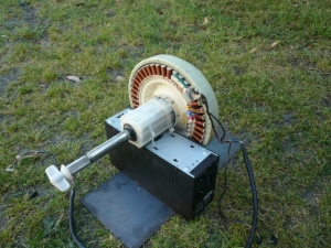
I made a little bit of progress on the recumbent bicycle front today. I’ve made a makeshift test stand for the Smart Drive motor so I can start testing some control board designs before I put in the effort of installing the motor on a bicycle frame. This way the motor has no load connected to it, which will keep the current required to run the motor to a minimum during testing.

The stand basically consists of the shell from an uninterruptible power supply (UPS), bolted to a piece of steel plate, with the nylon hub of the motor cable tied to the UPS frame. The first thing I did was strip the UPS frame and reinforce it with a couple of cable ties.

The bare UPS frame with cable ties to prevent it from wobbling.

Four matching holes were drilled into the cover of the UPS and a piece of scrap steel I bought for $5 and then they were bolted together using M4 bolts and nuts. I had to buy this piece of steel because, it wasn’t until after I gave the steel case of the washing machine to the scrap metal merchant, I realised I could of cut it out of that instead of having to buy more. But, that is a lesson learnt I suppose.

Lid of UPS bolted to steel plate using M4 bolts and matching nuts

Basic stand after UPS frame is bolted back into its lid and attached steel plate.

I then cable tied the motor hub to the basic frame through the holes that were already present in the bottom of the UPS. The motor does have a bit of movement after it has been secured. However, if this becomes an issue during testing I will probably just put some double sided foam tape down between the motor hub and the UPS frame to prevent it sliding about. Time will tell on that front.

The motor secured to the frame via cable ties around the motors bearing hub.

After all is said and done, I think I have managed to slap together a passable test stand that should get me through to the time that I have to actually mount the motor onto the bicycle frame.

Finished test stand. The steel plate was connected so that more of it was on the side that the motor would be on. Due to the centre of gravity of it not being directly over the hub, but underneath the actual motor. This way it stops the stand from falling over.


Maximum Temperature Test Probe

2 10 2012

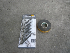
Today I’ve been working on a graphite probe to test the maximum temperature that I can achieve with the solar cooker I made. I went with graphite because it is black and it can handle extremely high temperatures without melting or breaking down. To make the probe I have used some graphite sticks I got from an art supply store and a high temperature thermocouple probe for my multimeter that I got from work.

Drawing graphite and double sided foam tape. The tape is used to hold the graphite in the vice on my drill press.

The specifications of the probe say that it is very accurate when measuring the temperature of a gas or a liquid. Since I am measuring the temperature of a solid, I decided to drill a hole into the graphite, fill it with solder, then insert the probe into it. This way the solder will melt and give accurate readings. I am hoping that I will still get some accuracy when the solder is still solid.

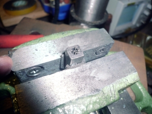
First I stuck some double sided tape onto opposite sides of one of the 8B graphite sticks so I could put it in my vice on my drill press without it shattering. I made sure to leave the backing paper on the tape so that it wouldn’t stick to the face of the vice. I used the 8B to start with because I wasn’t sure if I could manage to drill into graphite without it breaking.

Double sided foam tape (with backing paper left on) is applied to opposite sides of the graphite so the jaws of the vice don’t apply too much force and make the graphite shatter.

Next I put the stick of graphite into the vice as low as it would go and then drilled a hole down the length of it. I started with a 2mm drill bit and worked my way up to a 5mm drill bit. The diameter of the thermocouple is 4mm, so the 5mm hole allows enough room for the solder to surround the probe.

5mm hole drilled to accept the thermocouple with some space around it for solder.

Once the hole was drilled to a reasonable depth, I chopped off strands of 60/40 rosin core solder in the hole until I couldn’t fit any more in.

Hole filled with solder

I then melted the solder using a hot air gun. I had to add more solder afterwards until I had completely filled the hole and then I inserted the probe while the solder was still molten.Then topped off the hole because too much of the solder shot out when the thermocouple went in.

Probe inserted into the graphite and held in with the solder.

I made sure to have the probe connected to the multimeter while the solder cooled so I could read the temperature. After it had cooled to a temperature I could safely handle, I checked that the probe had a good solid connection with the graphite. All that is left to do now is fire up the solar cooker on the next clear day and give the probe a try.

Finished thermocouple probe. I’m not sure how accurate this will end up being because not all of the probe is inside the graphite, which could lead to a lower reading then it should be.


Making of a Cheap Solar Cooker

27 09 2012

This is a little side project I’ve been working on over the last few days. I’ve wanted to build a solar cooker for a while now, so when the opportunity came up to score this Ku Band satellite dish for free, I couldn’t resist myself. These dishes aren’t perfectly circular, but more elliptical, because they are designed to be the cut out of a circle projected onto a parabolic surface but slightly off to one side of it from centre. In this way, the horn that contains the receiver and transmitter is not in the way of the incoming signal. Hence, you get more surface area to collect the signal but, more importantly, you don’t get weird effects, like scattering, degrading the incoming signal.

Ku Band Satellite Dish with Stand

The first thing to do was to go into work and grab some aluminium tape and get cracking. I cleaned the surface first of course.

The aluminium tape I used

First strip on
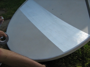
Curvature begins to be a problem

At this point the curvature of the dish starts to cause a fair bit of ripples in the tape, it also begins to get harder to line up the tape for a straight run across the dish. So, I changed to applying the tape vertically, in line with the major axis, instead of horizontally, in line with the minor axis.
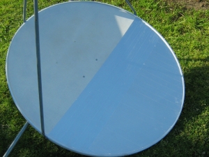
Halfway there.

My five year old taking a photo of me whilst I am working. He does love cameras.

The dish with the reflective surface finished

As you can tell from this photo, obviously mirrors would have better reflectivity. But, I don’t really feel like cutting that many square pieces of mirror and then attaching them to the dish. This was much easier and will get a similar result cooking wise. If I were building a solar powered metal foundry, as at one point I have planned to, then I would rethink my choice.

After this, I removed the horn and then flipped the mount on the back of the dish around. I did this so I could have the focal point above the dish, instead of in front of it. That way I would get the sun light concentrated onto the bottom of my cooking pot, instead of on the side, which will allow for more even cooking.
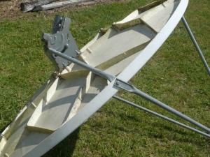
Dish mount in original direction


Dish mount in new direction

Next, I tied a rope between the main boom of the stand, that came with the dish, and one of the support legs because I had problems with it sliding out when I tried to mount the dish on it.
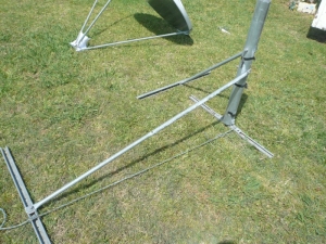
The stand that came with the dish

The dish is all mounted and ready to go

Once it was all together, I had a little bit of fun with a piece of paper. The reflector didn’t have enough power to burn through plain white paper. But, if you put a black dot on it, using a permanent marker, then it catches on fire pretty much straight away.

*insert evil laugh here* IT WORKS!!!
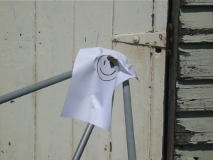
I can’t believe he’s still smiling after that.

After I had my bit of fun, I attended to the problem of being able to hold a pot at the focal point. I ended up using a section of wire fencing I had laying around for my initial tests but I may end up making a hanging arrangement later on. This is because I’m not too sure how it will go during late afternoons or early mornings when the Sun is lower in the sky. All the contents may shift to one side and spill out. That will be one test for a later date.

All I had to do to mount the cooking rack was take off the coupler that is used to hold the horn and the three support legs together. Then slide the poles through the holes in the rack, then re-attach the coupler. With this set up, the rack is held in place very well by the support poles attached to the minor axis, but moves a bit up and down on the pole attached to the major axis. This may actually help in the long run, as it will allow for a little bit of adjustment when trying to make the cooking pot level.
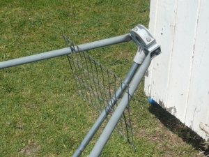
Cooking rack installed

I then did a test to see how long it would take for the cooker to heat up 500mL of water in the pot I bought ages ago just for this purpose. I got the pot in a set of two for AUD$5 from a local clearance store. Mainly because they were cheap and had a black enamel coating on the bottom. This greatly enhances the effectiveness of a solar cooker due to the black absorbing more of the incoming radiation and, hence, transferring it into more heat energy for cooking.

Solar cooker aligned and with cooking pot in place.

The pot only just fits in between the support poles and required a little bit of wriggling to persuade it into place. You can see the yellow thermocouple I used to measure the temperature of the water in this picture. At the end of the experiment, I realised that either the thermocouple isn’t very accurate at measuring temperature, or the multimeter I used it with isn’t. Because, when the water was happily boiling away, I was getting a reading of only 97.6 degrees centigrade not the 100 degrees that I was suppose to be getting.

500mL of water boiling vigorously.

It only took approximately 14 minutes to get the 500mL of water to fully start boiling. So, I call this a massive success. I can’t wait to see how this thing performs in the middle of an Australian summer.

After I finished testing, I took a measurement of the ambient air temperature with my multimeter and compared it to the reading from my cheap wireless weather station that I was using for timing. The weather station took a reading of 29.2 degrees C whilst the multimeter took a reading of 24.8 degrees C. Considering my weather station is one of the cheapest available, with only indoor and outdoor temperature readings as well as humidity and barometric pressure, I don’t think it is giving a very good reading either. But it does illustrate the inaccuracies that I didn’t foresee at the start.

Anyway, here is a plot of the data I acquired during testing and a copy of the spread sheet I wrote up to go along with it.
One thing I did notice is the linearity of the plot. I must admit that I was expecting it to trail off at the end but it didn’t. This would imply to me that this thing has a lot more potential for heating up more things then just water. I’m going to try and find a carbon brick from somewhere and heat that up. That should give me a real idea of its true power.

Plot of the time it took for 500mL of water to reach full boil.

Water Boil Test

I think I’m going to have a bunch of fun with this in the future.


Fisher and Paykel Smart Drive Schematic

25 09 2012

I’ve spent my free time over the last few days reverse engineering the control board out of the Fisher and Paykel washing machine I bought. I managed to find details on all of the components except one. I know it’s a MOSFET but, beyond that, I don’t have any more specifications. It is labelled H75309 G814BE and is a 4 pin SOT-223 package. If anyone has any more information on it, I eould very much appreciate it. I used this codebook to help find all the parts with SMD markings on them, which was exceptionally helpful and I would highly recommend it. I rewrote the schematic in KiCAD (Build: (2010-00-09 BZR 23xx)-stable), which I will share with you all here. Please note that this is not a complete schematic of the control board but only a partial of the power section that drives the motor. I wasn’t really interested in the rest of it and it took a long time just to do this part. So, I’m not going to bother doing the rest, except for the hall effect sensor section at a later date. I’ve also included the libraries I created for the parts that KiCAD didn’t have as standard. They must be added to your library list before the software can use them.

Next, I’m going to attempt to remove as many parts as I can off the board to reuse, then use them to develop a prototype for my controller. Hope this all helps somebody.

smart_drive_controller